GPS
June 19, 2014
In today's lecture I learned more about GPS. Firstly, GPS consists of 24 satellites at a height of 20,000km (This is 1/2 of geostationary satellites which are at a height of 40,000km). GPS satellites have orbits of 12 hours. At least four GPS satellites are required for triangulation and all GPS satellites transmit the same 2 frequencies.
Next, I learned about correlation. Correlation can be determined by three ways: Correlated, Anti-Correlated and Uncorrelated. An example of Correlated is shown in Figure 1.
Next, I learned about correlation. Correlation can be determined by three ways: Correlated, Anti-Correlated and Uncorrelated. An example of Correlated is shown in Figure 1.
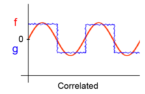
Figure 1: An Example of Correlated Waves
One example of Uncorrelated waves are shown in Figure 2.
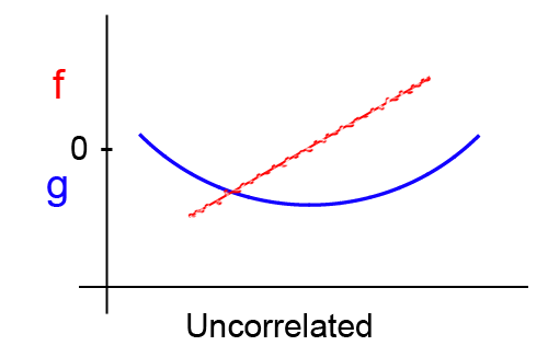
Figure 2: Second Example of Uncorrelated Waves
Finally, an example of Anti-Correlated waves are shown in Figure 3.
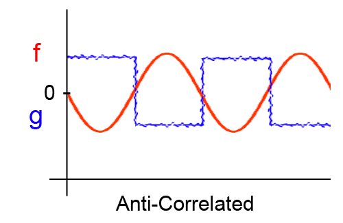
Figure 3: An Example of Anti-Correlated Waves
The relation and equation for "f" an "g" (Shown in Figures 1-3) is explained in Figure 4.
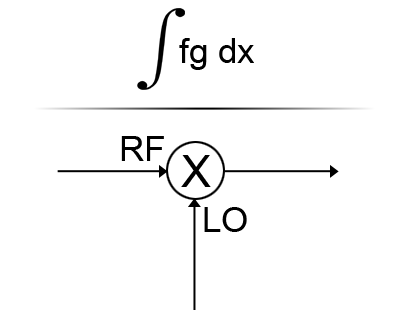
Figure 4: The Equation of "f" and "g" and the Multiplier which Relates them
Next, I learned about Pseudo Random Codes (PRCs). For GPS, there are 24 PRCs which are 1023 bits long. The way GPS works is the transmitter has 1 PRC and the receiver has the 24 PRCs. The transmitter takes the first PRC from the receiver and compares it to the transmitter's single PRC. The receiver's PRC is moved left to right to compare with the transmitter's PRC. If it does not match up, it moves onto the next PRC. If this, again, does not match it moves onto the next PRC until all 24 are checked and the correct one is found. An example of this process is shown in the animation below in Figure 5.
Figure 5: Animation Showing the Receiver Comparing its PRC (Bottom) with the Transmitter's PRC (Top)
Next, I learned more about the GPS Transmitter. Each satellite carries a 10.23MHz cesium clock. Furthermore, the L-Band consists of 2 frequencies:
- L1 = 1.5742 GHz
- L2 = 1.2276 GHz
Course/Acquisition or Clear/Access (C/A) code repeats every millisecond. Figure 6 shows the GPS transmitter and all its signals.
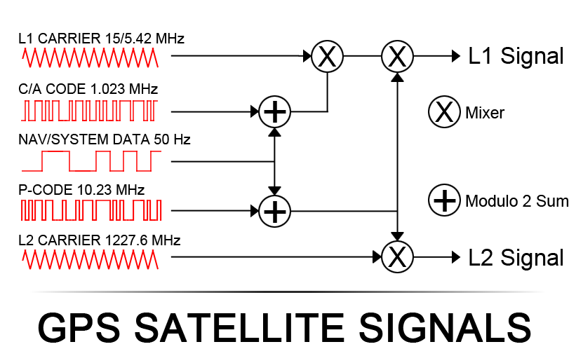
Figure 6: GPS Transmitter and Signals
July 24, 2014
Today we took a look at Binary Phase Shift Keying using the BinaryPSK.dat file for the Signals2014 program. Phase shift keying (PSK) is a digital modulation scheme that conveys data by changing, or modulating, the phase of a reference signal (the carrier wave). Refer to Figure 7, below, for an example of Binary PSK in Signals2014.
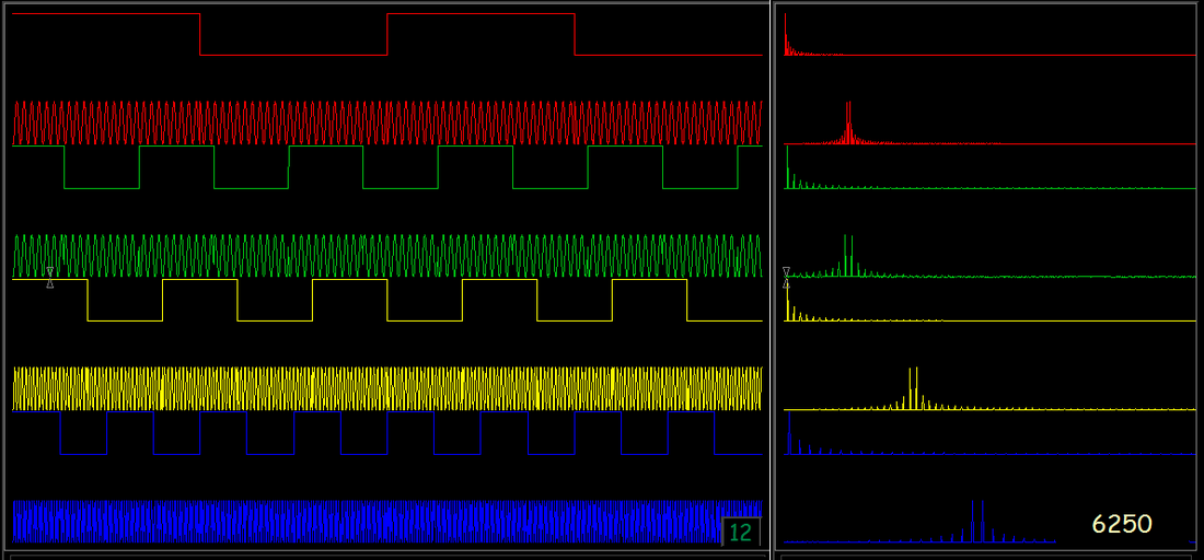
Figure 7: Binary Phase Shift Keying Example shown in Signals2014
